Wiring: Power Adapter to Coinslot
Check for the coinslot label
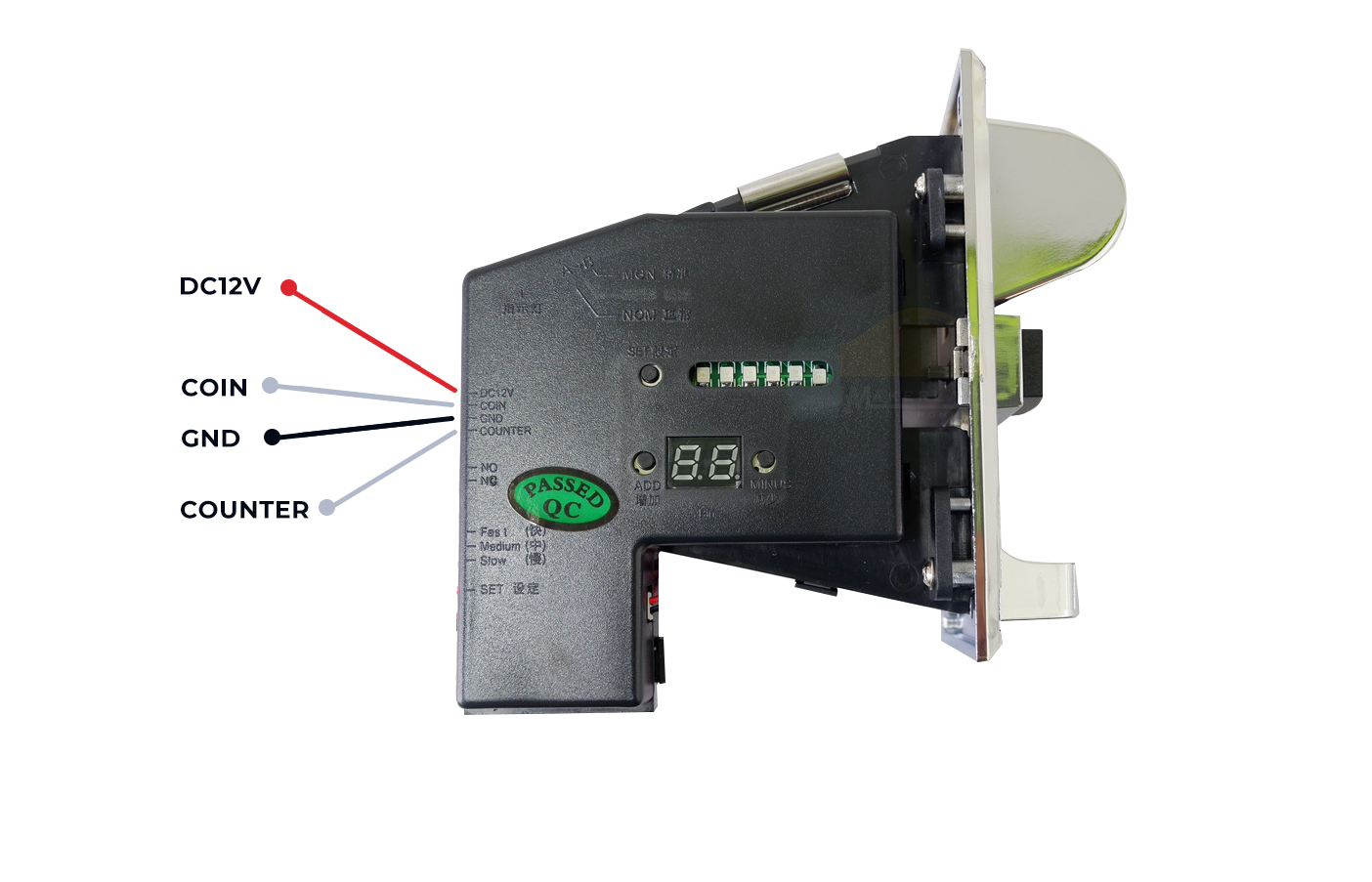
- DC12V
- COIN
- GND
- COUNTER
At the back of the coinslot, you should be able to see some sort of 2 switches. Set each specifically to the following labels:
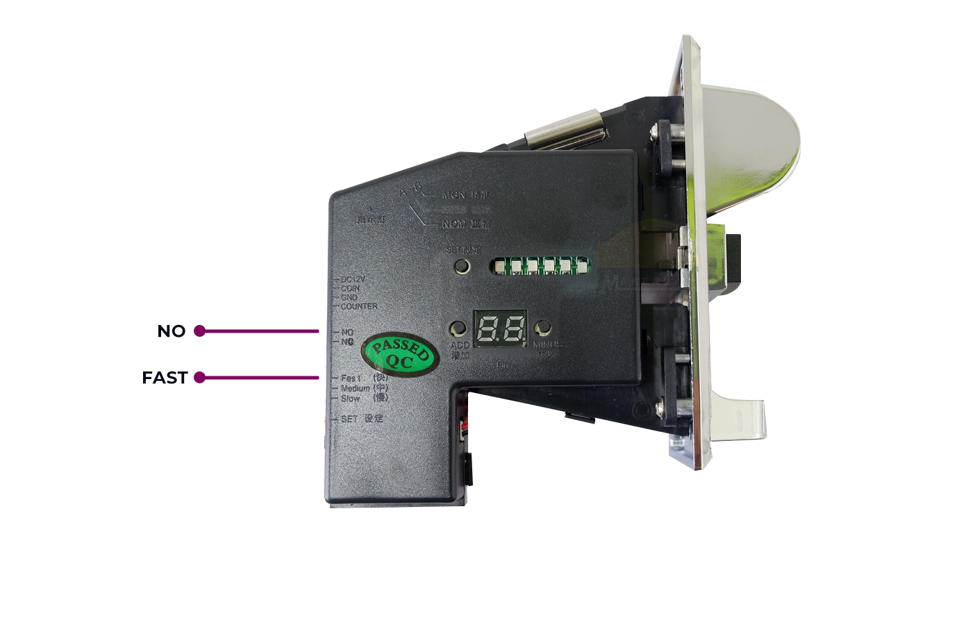
- FAST
- NO
Red
Gray - not needed, remove this wire
White
Black
Now let’s get started with the actual wiring.
Check and sort out the wires (should be included as coinslot package). For this example, we have wires in the following colors
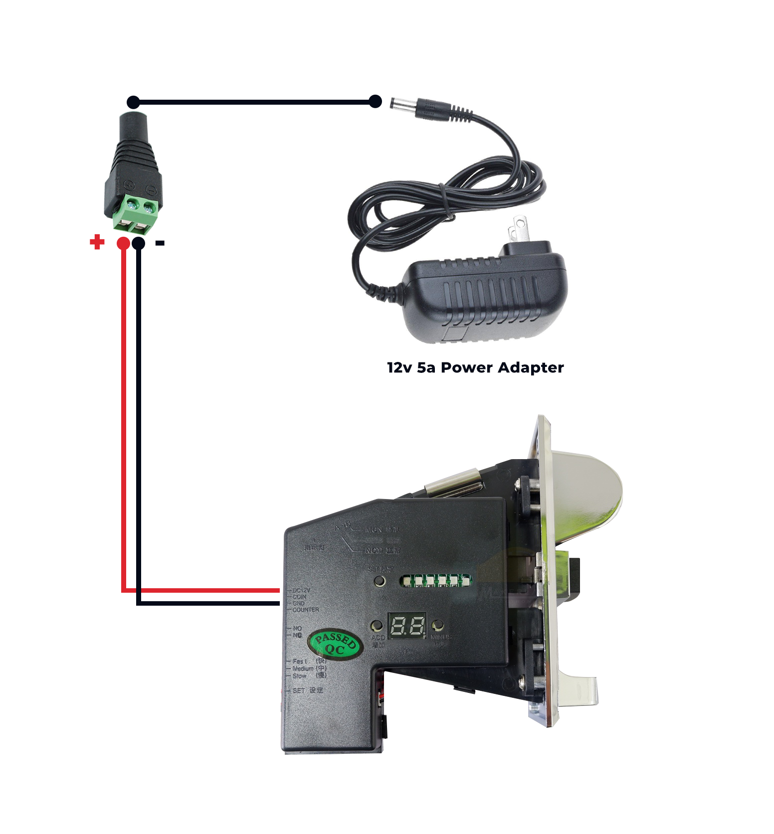
- Connect Red Wire to Female DC Jack’s “Positive” (+).
- Connect Black Wire Female DC Jack’s “Negative” (-).
- Insert Red Wire to Coinslot’s “DC12V” Pin.
(The “White Wire” will also be inserted into Coinslot's “Coin” Pin). - Insert Black Wire to Coinslot’s “Ground” Pin.
Your coinslot should be ready to power up. But let’s continue with the wiring for the Power Adapter to Board first.
Next:
Wiring: Power Adapter to Board