Wiring: Power Adapter to Board
From the previous step, Wiring: Power Adapter to Coinslot, you’ve already connected a Red Wire to DC Jack’s “+” and a Black wire to DC Jack’s “-’.
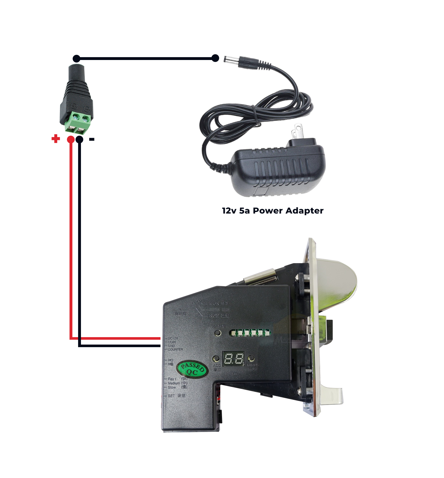
You’ll need another wires to splice it to the Red and Black Wire (connecting the Female DC Power Jack Adapter and Coinslot).
- Using another wire (preferably red to easily identify), splice one end of this wire to the “Red Wire” that is connected from Female DC Power Jack Adapter’s “Positive (+) ”.
- And using another wire (preferably black to easily identify), splice one end of this wire to the “Black Wire” that is connected from the Female DC Power Jack Adapter’s “Negative (-).
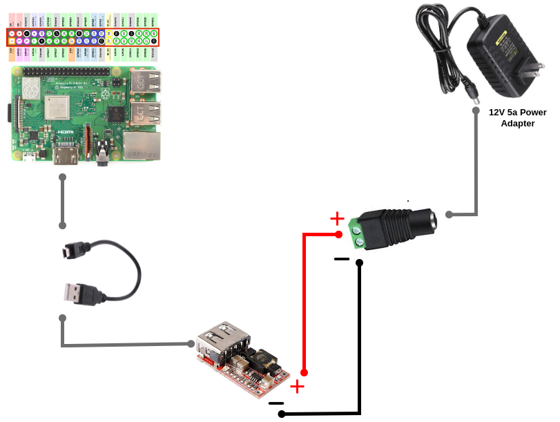
- Connect another end of the spliced “red wire” to Buck Converter’s “Positive (+)”.
- Connect another end of the spliced “black wire” to Buck Converter’s “Negative (-)”.
- Connect the power cord from buck converter’s USB Port to the board’s micro-usb power input.
Your board should be ready to power up. But let’s proceed to “Wiring: Coinslot - Board'' first.
Next:
Wiring: Coinslot to Board